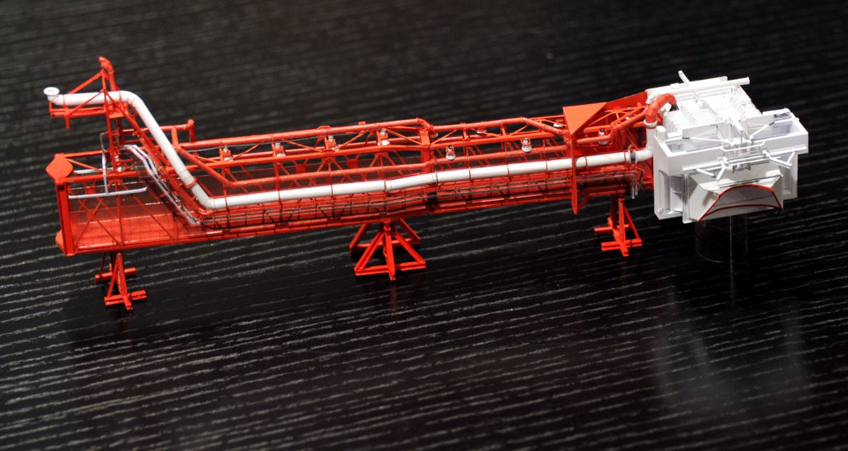
Test build of the Command Module Service Arm
- Mischa
- LUT model
.... whereby I will also partly use the laser cut parts to test their processibility
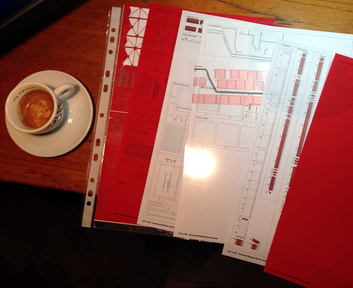
Command Module Service Arm kit printed
A lot of things had to be redesigned and most of the laser parts no longer fit. The red tone of the printed parts does not match 100%, because they were calibrated for an ink jet printer, but I used the laser printer. However, in natural light it is hardly noticeable and the structures are relatively small.
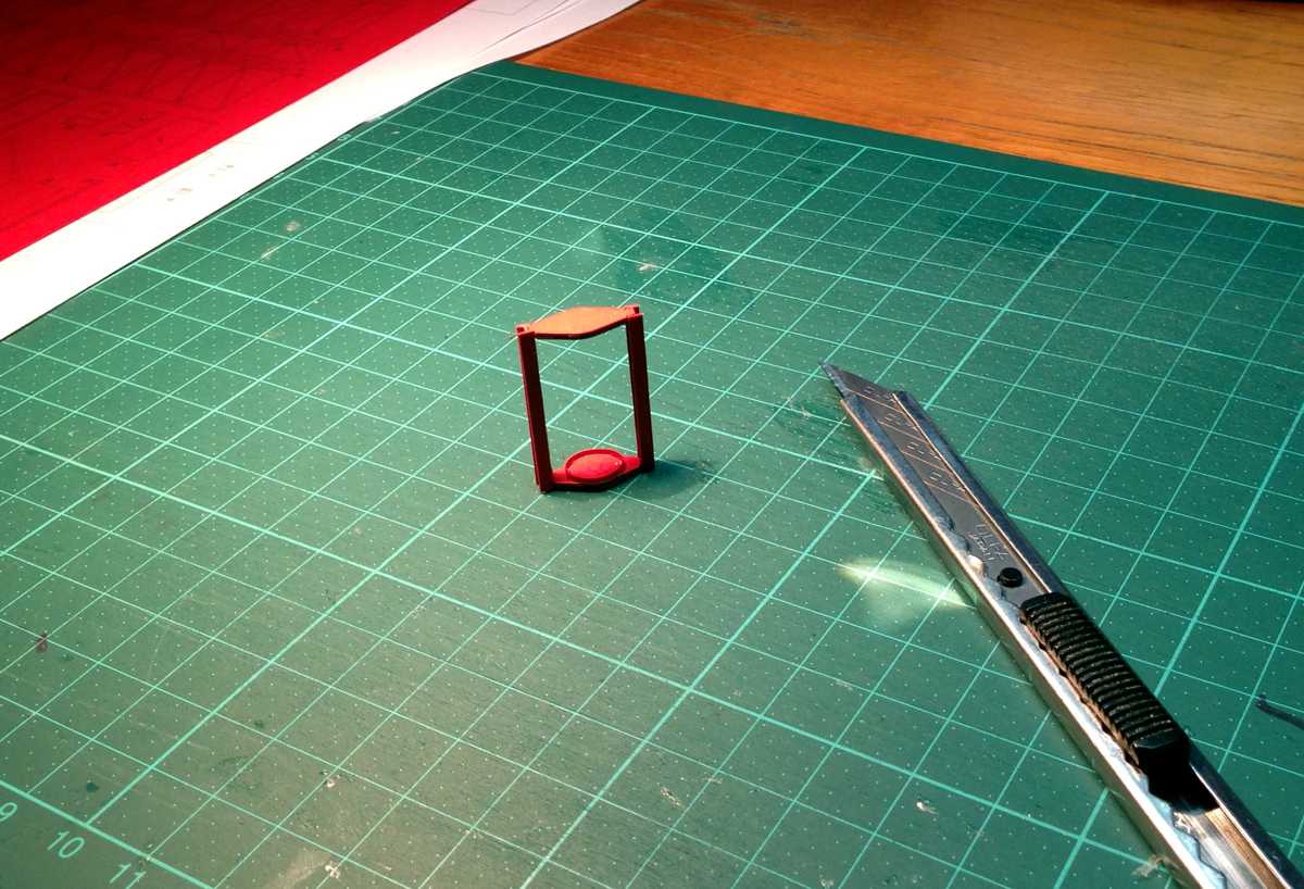
Hinge
A real swing arm has to have a joint, of course. So here is the arm-side connection to the hinge. It should be manufactured as precisely as possible, because otherwise the swing arm frame distorts, especially since Command module service arm is very long. My fingers, which have become clammy from everyday construction work, admittedly have trouble getting into modeling again.
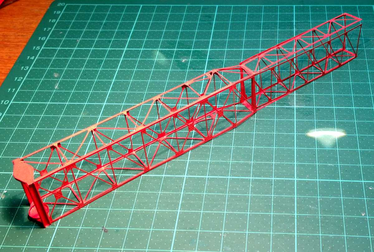
Command Module Service Arm basic frame
Here is my premiere: the first laser part of my life. Folding is a highly subtle affair, a little more sharpening is needed. The cut in the middle was too deep on the other hand, because scoring and engraving had a devastating rendezvous here, and their combination didn't serve the paper too well. The side parts of the front section were cut off smooth, I have now added them provisionally. Fixing the hinge to the arm frame is also very tricky, because you have to make sure that everything is exactly right. The best way is to place the base plate exactly and then glue the roof plate first.
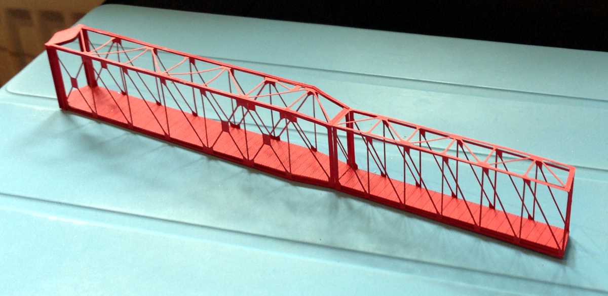
Command Module Service Arm basic frame
Here the basic frame on the cover of an iPad. Clearly visible is the vertical gap between the front and back part that the laser has left in its cutting frenzy. Fortunately, the edges and the base plates already leave an amazing stability.
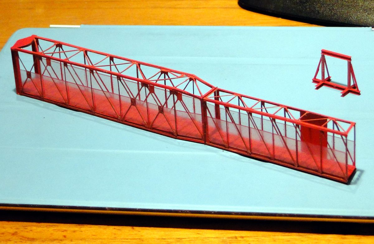
Command Module Service Arm basic frame
... optically not much has changed yet, which makes the laborious doubling of the stiffeners a true Zen exercise. The struts are hardly eye-catching, and if they are, they are rather conspicuous by microscopic adhesive residues that, despite their tiny size, have the strange characteristic of jumping into the viewer's eye like grains of sand. Nevertheless, the effort is worthwhile, the stability of the frame is much better, and any distortions dissolve into pleasure.
There is a lot to correct on the railing grids, the rear ones are too long, they have to be flush with the joint part, and the front left one is also too long - I hadn't considered that the front part of the arm is slightly sloped, and the copy&paste abbreviation was used. And last but not least - the slanted section in the middle should not be separated, but connected to the rear railing grid, so the build is much easier.
In the background you can see the first of the three display stands, which will soon go into action, as the MSS cover has a beam and the arm does not lie flat once it is applied.
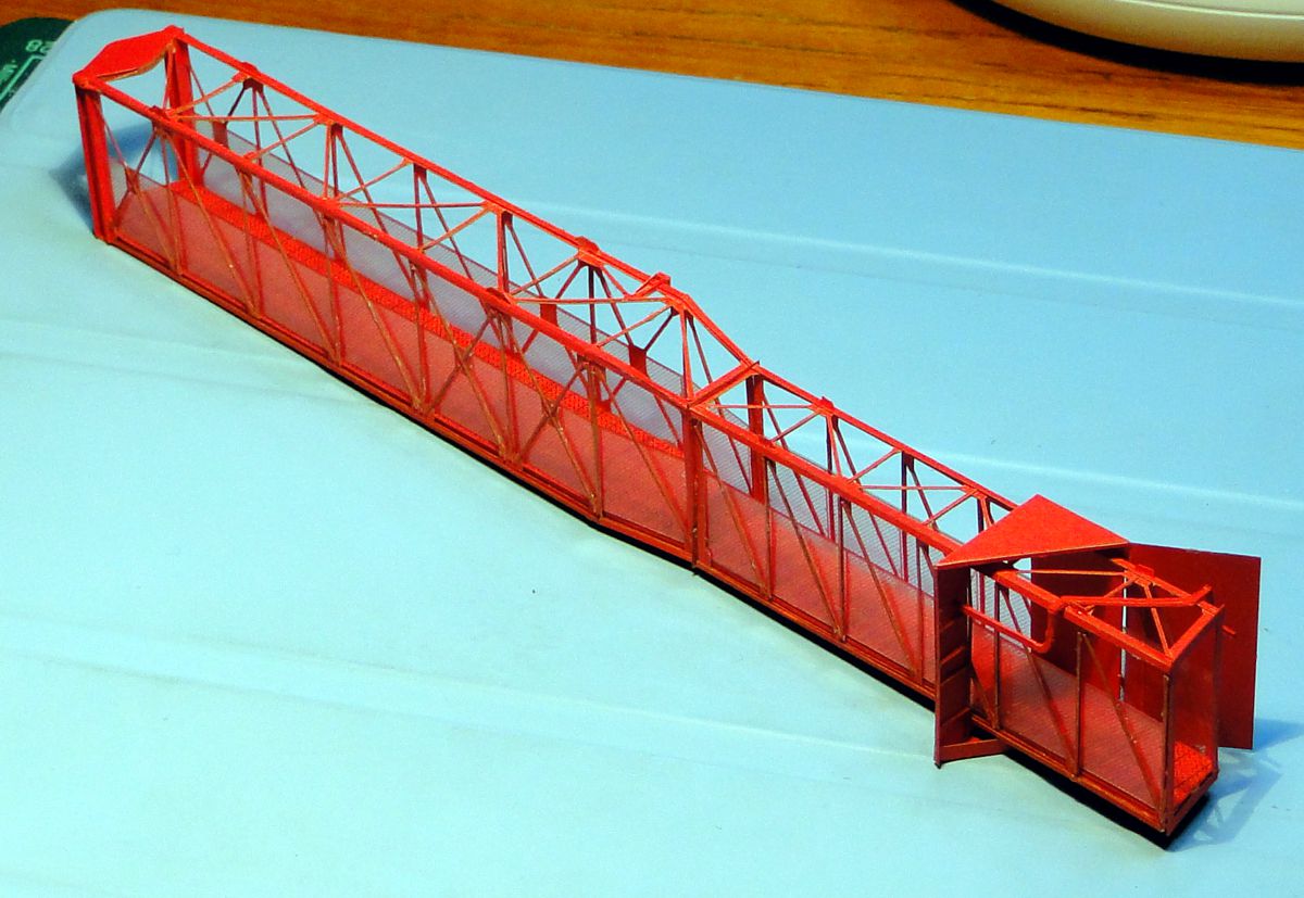
Command Module Service Arm basic frame with MSS protection cover
The MSS protection cover and several tiny particles have been added. For the particles (parts 36 to 48) - they are mainly intended as add-ons for the insane, only parts 37 and 41 are really essential. All others can be omitted, they are hardly perceptible, and the glue residues they may cause are usually better visible than the part itself.
As a courtesy I have tried a few, the result is ok. I used the MSS cover (part 20) as a laser part, because it is one of the few parts with a longer valley bend. And here the laser cut is really amazing - mountain and valley bends are completely equal. The cut is more accurate than the police allows, I didn't manage to pull the part over the arm front as intended, and finally had to cut the frame at the bottom. Basically no problem, because it's not visible afterwards, especially if you glue a paper strip of the same width over it.
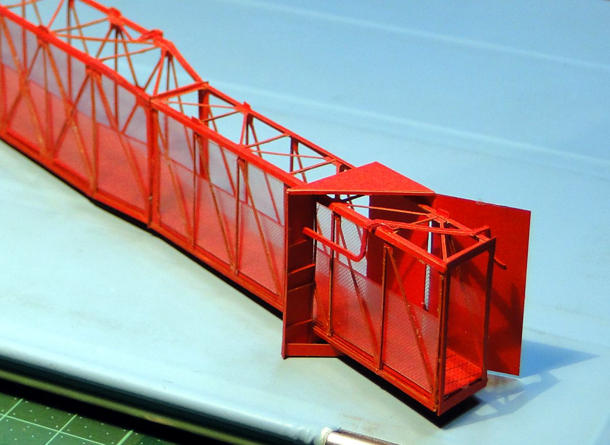
Command Module Service Arm basic frame with MSS protection cover
The handling of the horizontal ribs on the inside of the cover is a bit *uhm* eccentric, which is due to the way the cover is folded - they belong to the back side of the print. So there is no reference for the gluing position - I put it on the two sidewalls. So you have to build a ladder and glue it to the cover - a pretty stupid procedure, admittedly. As a reward it's hardly possible to get the ribs 100% parallel, which is more disturbing on the photo than in reality, and moreover it won't be visible on the finished model anymore, because between the ribs pipes and cable connections sprout, which mercifully cover the inadequacy.
As a small anticipation I have already attached a pipe (WDR.14) to test if it can be peeled out of the 300g paper. Works well (especially thanks to the magnifying lamp), and the effect is great - the thick paper makes the part much more plastic, which comes across much better on the real model. So I will use 300g cardboard for all 'flat' tubes (diameter smaller than 6") at the LUT.
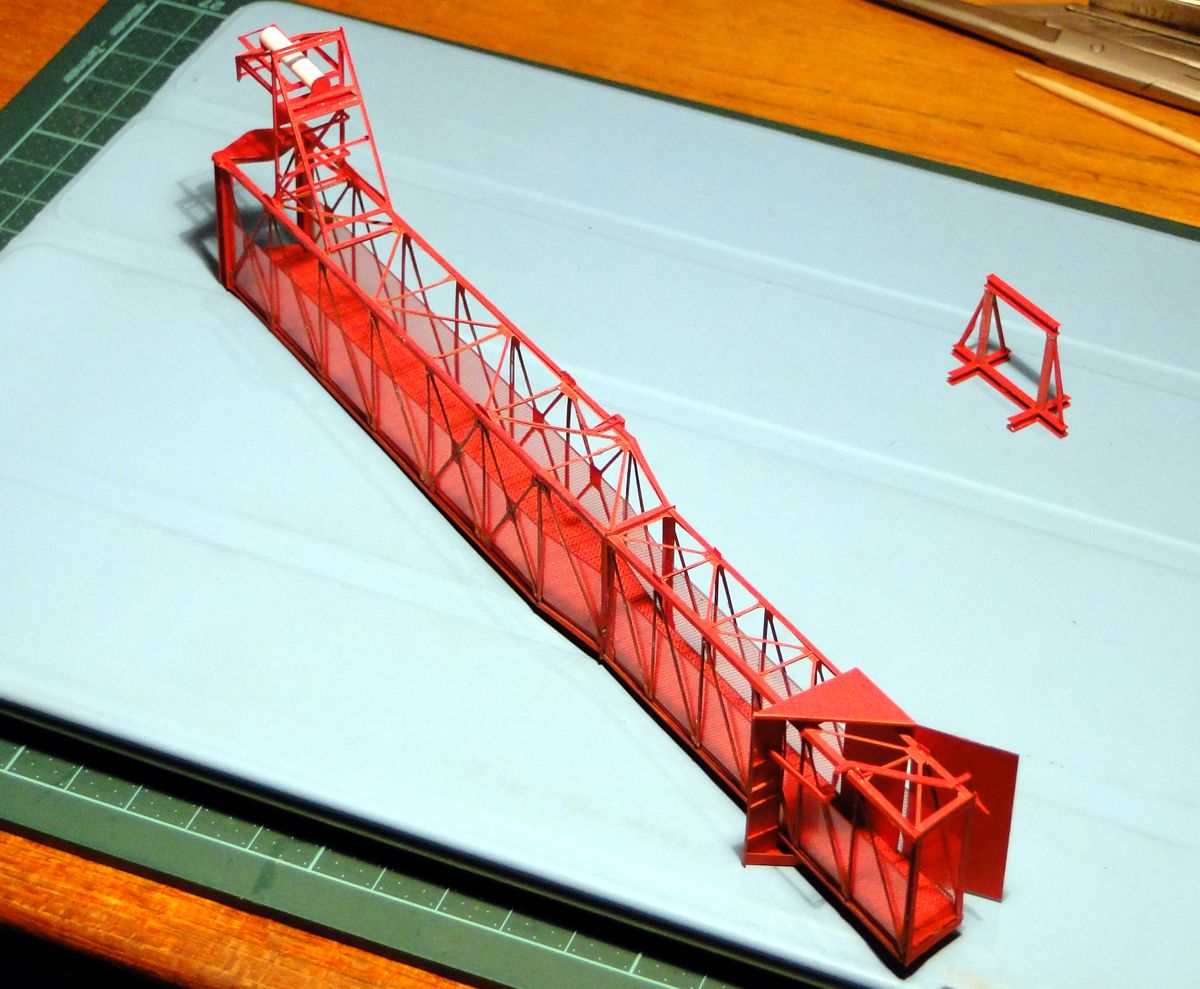
Command Module Service Arm basic frame withcable support tree
The support tree is entertaining to build, full of thrills and many curses. You can hardly touch the filigree web anywhere without liquidating the microscopic glue spots. At some point you don't care anymore and put your adhesive tightness aside. The main thing is to fix the part. Somehow.
Oh yes:
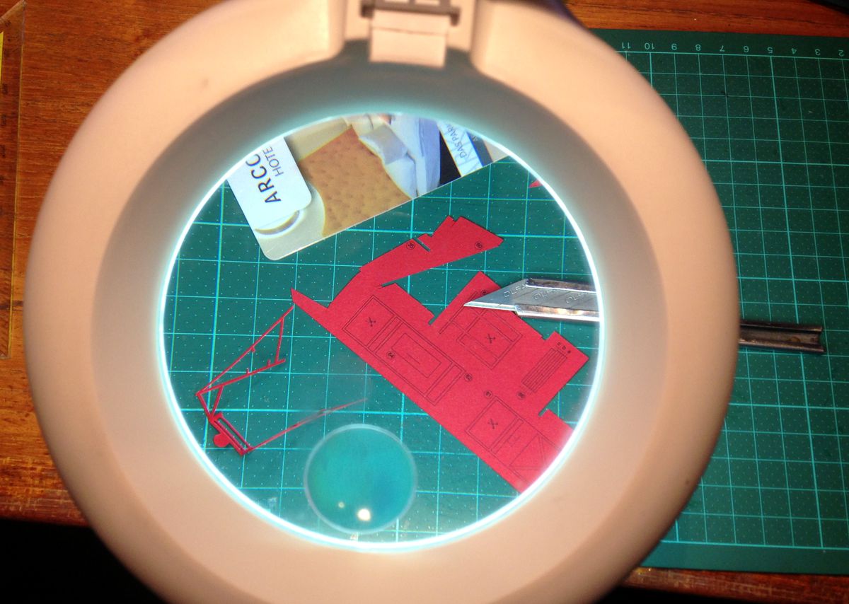
My magnifying glass lamp
The tree is hand cut, as you can see. A hotel room card serves as a ruler. In one of my past lives, I once asked my men's outfitter Robert 'Roko' Kofler, to find or manufacture such cards transparent or translucent. The model builders of the whole universe would rip them out of his hands. Not to forget my magnifying lamp. Cutting difficult parts is a real delight, together with the 30° OLFA blades.
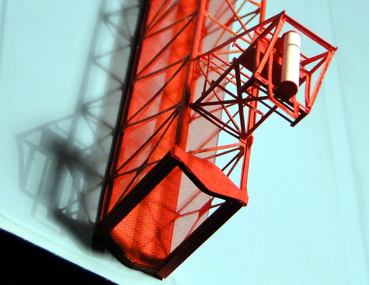
The cable tree
It is recommended to assemble the AC-Pipe from the back to the front and to install the corresponding pipe section as well, as long as the opportunity is favourable.
Only when the tree was firmly fixed to the arm did I realize that a ceiling light had to be installed underneath. Well. What would life be without challenges?
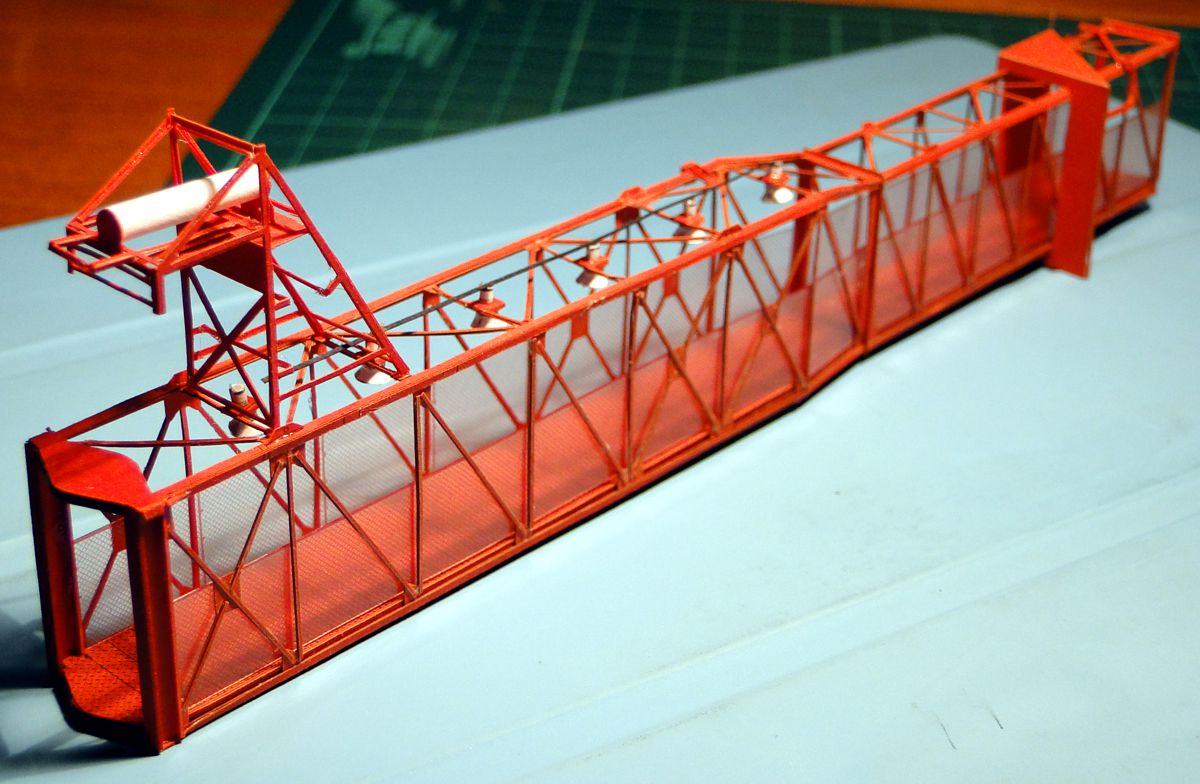
The lamps
Fiat LUT - uhm - LUX. As passionate followers of this blog know, there are thousands and thousands of lamps at the LUT, and most of them I have cancelled. On the service arms, however, they are clearly visible and therefore a merciless part of the kit. Actually, they should be installed prior to the cable support tree, installing the rearmost lamp afterwards belongs clearly to the cardboard construction-technically dispensable experiences, and the pleasure gain is very poor. Otherwise, the main difficulty is not so much the one-off production, but rather the even arrangement of the micro lamps, since even the slightest dance from the series causes considerable pain to the eye of the beholder.
What you hopefully missed - the power cable is too short, and ends in front of the rearmost lamp. I had blackened it on the underside with a felt-tip pen, so the length of the cut was no longer visible. Unplugging the cable again could mean the end of the model. So I leave it as it is, because it is not noticeable on the finished model anyway.
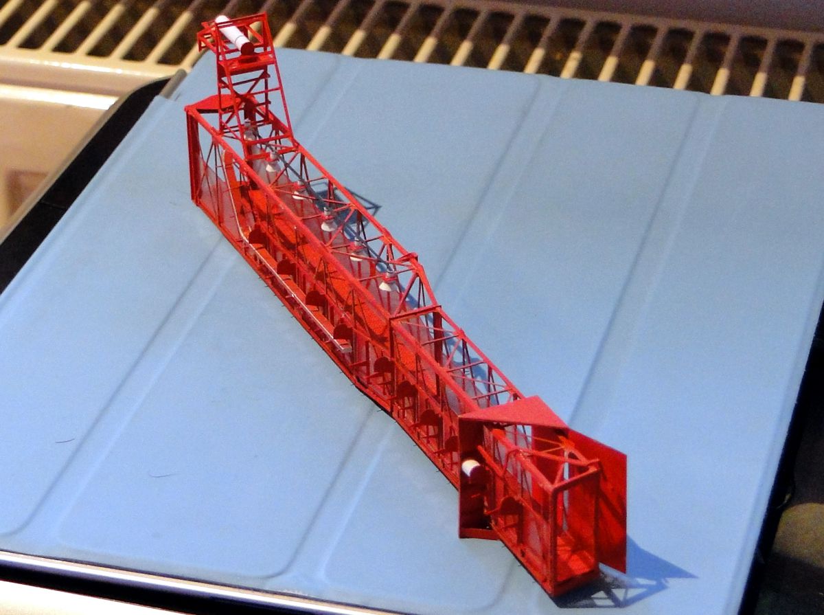
The support rack
The Support Rack is comparatively relaxed to build, and even if the straps are not 100% parallel it is not a big mishap. Firstly, once all structures are attached, they are hardly visible anyway, and secondly, their alignment can be corrected within certain limits during the assembly of the cable tray using the markings attached there ...
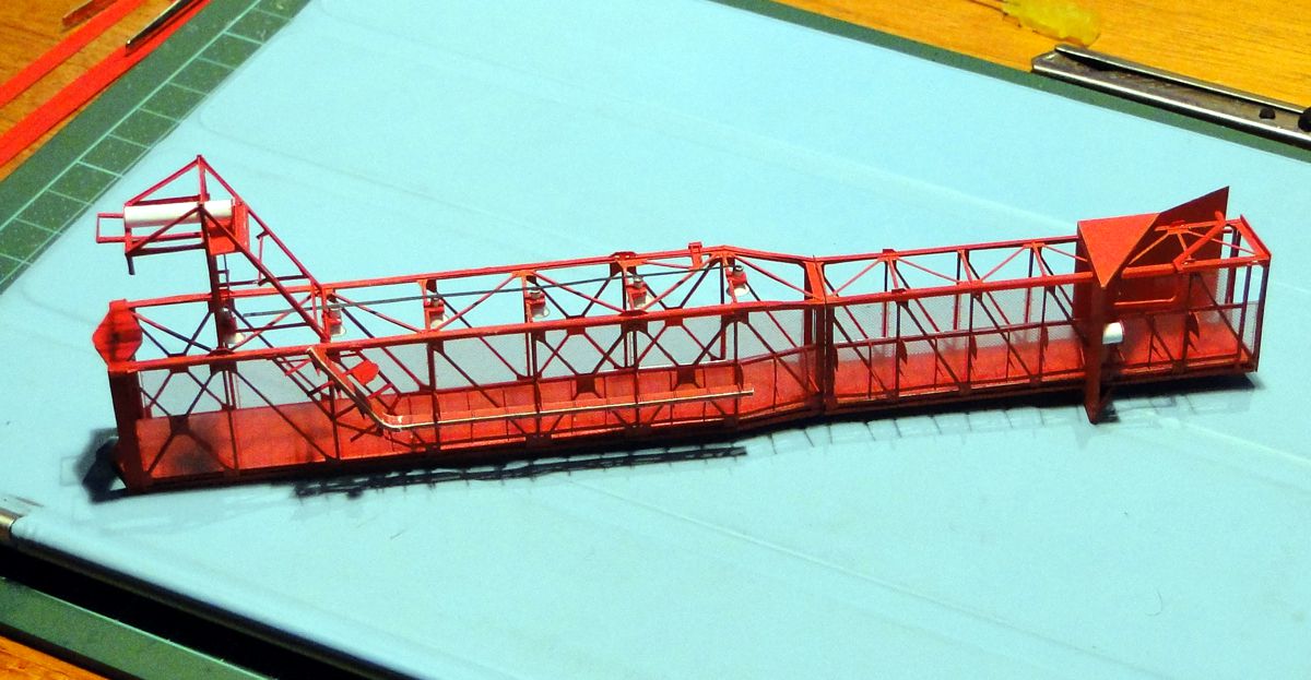
The support rack
... as visible here by the shadow cast, which looks very neat in the rear section, where a part of the cable tray is already attached, in contrast to the front section, where the straps are still somewhat confused. Part 1 (ESS.01) of the support rack gets a small redesign - it is united with part 2 to a single part, which makes the installation much easier. Why the parts are separated at all, has historical reasons, whose obsolescence did not let the designer think far enough *ggg*.
When installing the rack directly in front of the MSS cover, it is advisable to install the pipe segment of the AC pipe (the white plug in the picture) at the same time, as it is very difficult to install afterwards. Otherwise, however, the cable tray should be attached first to trim the straps and, of course, also because of the stabilizing and beneficial effect.
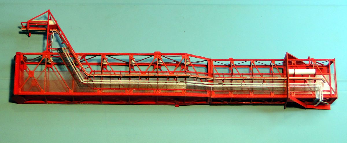
The support rack
The mounting of the pipelines is relatively laborious. The upper compressed air pipe almost destroyed my support tree, because its installation there is a very subtle matter and a swab of UHU in the wrong place quickly leads to disaster. The paper cable was too far to the left, where room for the water pipes is needed. The removal ruffled the support tree very hard, fortunately it could be revived by careful bending and treatment of the multiple fractures.
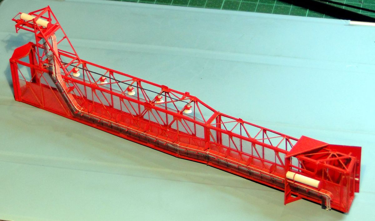
The support rack
The hair-thin hydraulic lines are printed on transparent foil - a small test for the LUT to assess the effect. On the photo they appear more accentuated than in nature and look quite natural. Which paves the way for some nice extra details. I also like the method of cutting the AC tube to make the red binders more plastic so far - but the longitudinal alignment of the tube becomes quite a challenge.
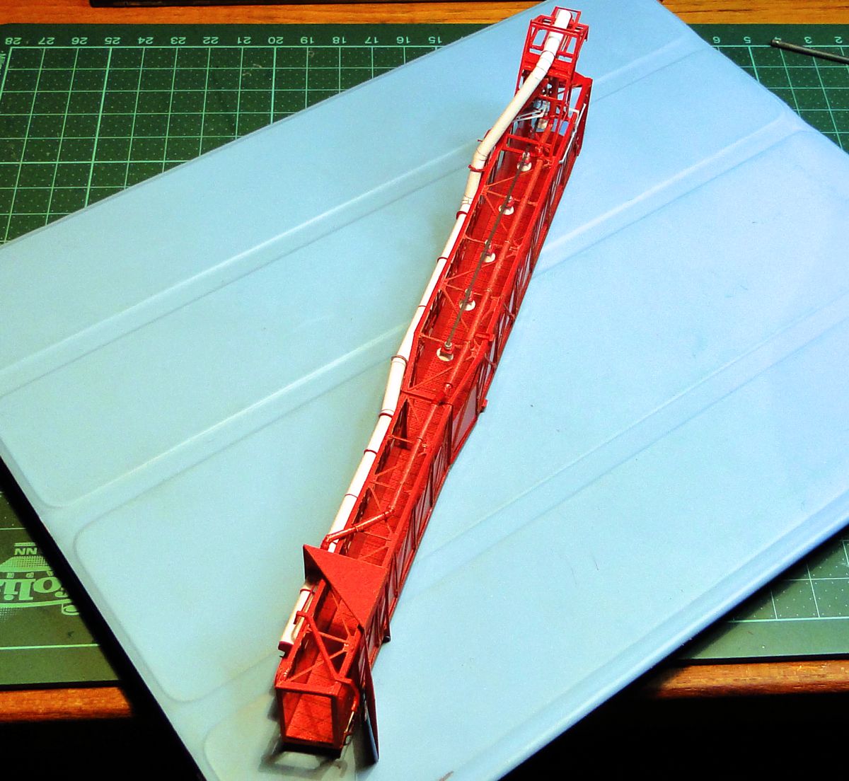
Water deluge pipes
The 6" water deluge pipes are designed to completely destroy a mentally stable model builder. Especially the bends are a chapter on its own. A bad chapter. I was wondering if this could be done easier. The answer is - go through it with humility, or use different materials like plastic tubes or wire. Other alternatives do not occur to me.
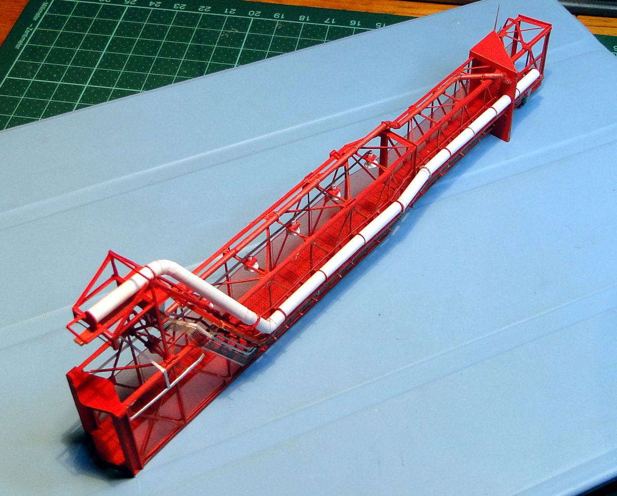
Water deluge pipes
Because. Once attached, the tubes simply look brilliant. We are talking about the red water pipe on the roof of the arm. The white AC pipe shouldn't cause any major problems. But the red color forgives a lot - minor mistakes are almost completely ignored in the three-dimensionality. The most important thing is the straightness of the pipe run. Every deviation immediately catches the eye without any sense of humour.
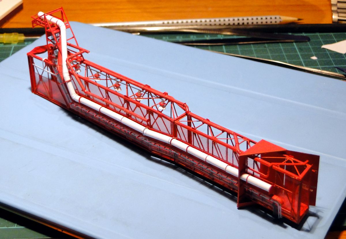
Water deluge pipes
The right water pipe originates from the left one, which also continues to the back towards the hinge and feeds the sprinklers there. Anyway, the construction seems to be improvised, which it probably is; it might have to do with the tragic events of Apollo 1, because the upper water pipe continues after the passage of the MSS cover over the White Room, and probably served there as an additional sprinkler in case of another fire event. The construction of the pipelines is, as before, a bit borderline, but I get more and more routine.
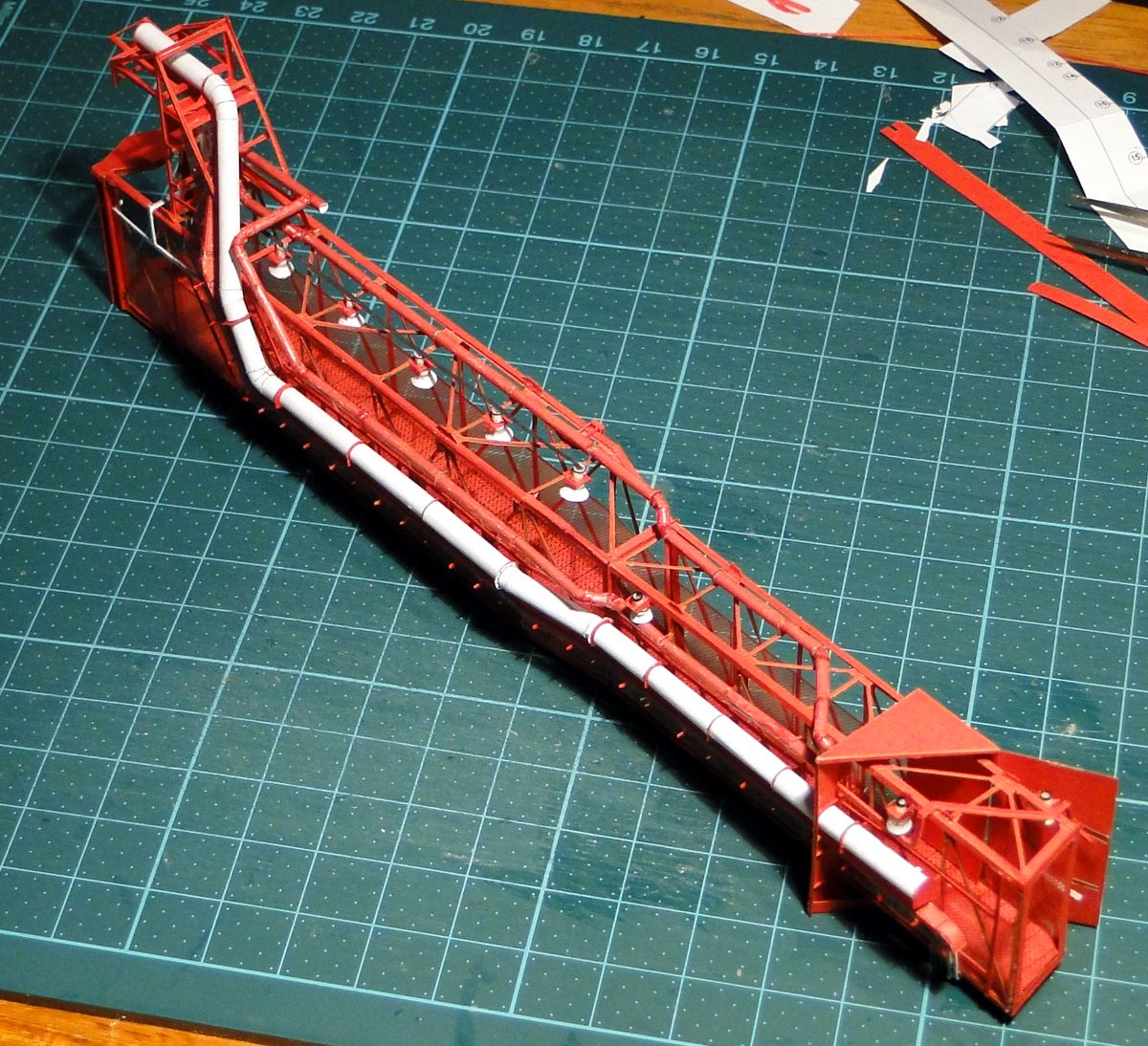
Water deluge pipes
The right water pipe is finished. As you can see here, it tapers to 4" as it passes through the MSS cover, a caliber that I only model as a paper strip to avoid challenging the resentment of the cardboard makers.
Yes, the side spots. They come quite close to the pipe, another indication that the water pipes were added later. In the model they were definitely too close, I plucked off the first lamp again and glued it vis-a-vis to the very front on the left where it fits anyway. In order to make them fit at the right side, I halved the height of the lamp's base, getting an extra half a millimeter. Possibly I also put the pipeline a bit too high, but this is almost negligible ...
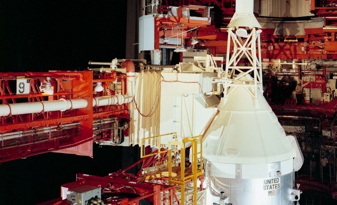
Courtesy of NASA
... like here in the original clearly visible. The lamps were definitely mostly lighting the pipes *ggg*
Also clearly visible is the flange I spared for easier building. I am actually much too nice.
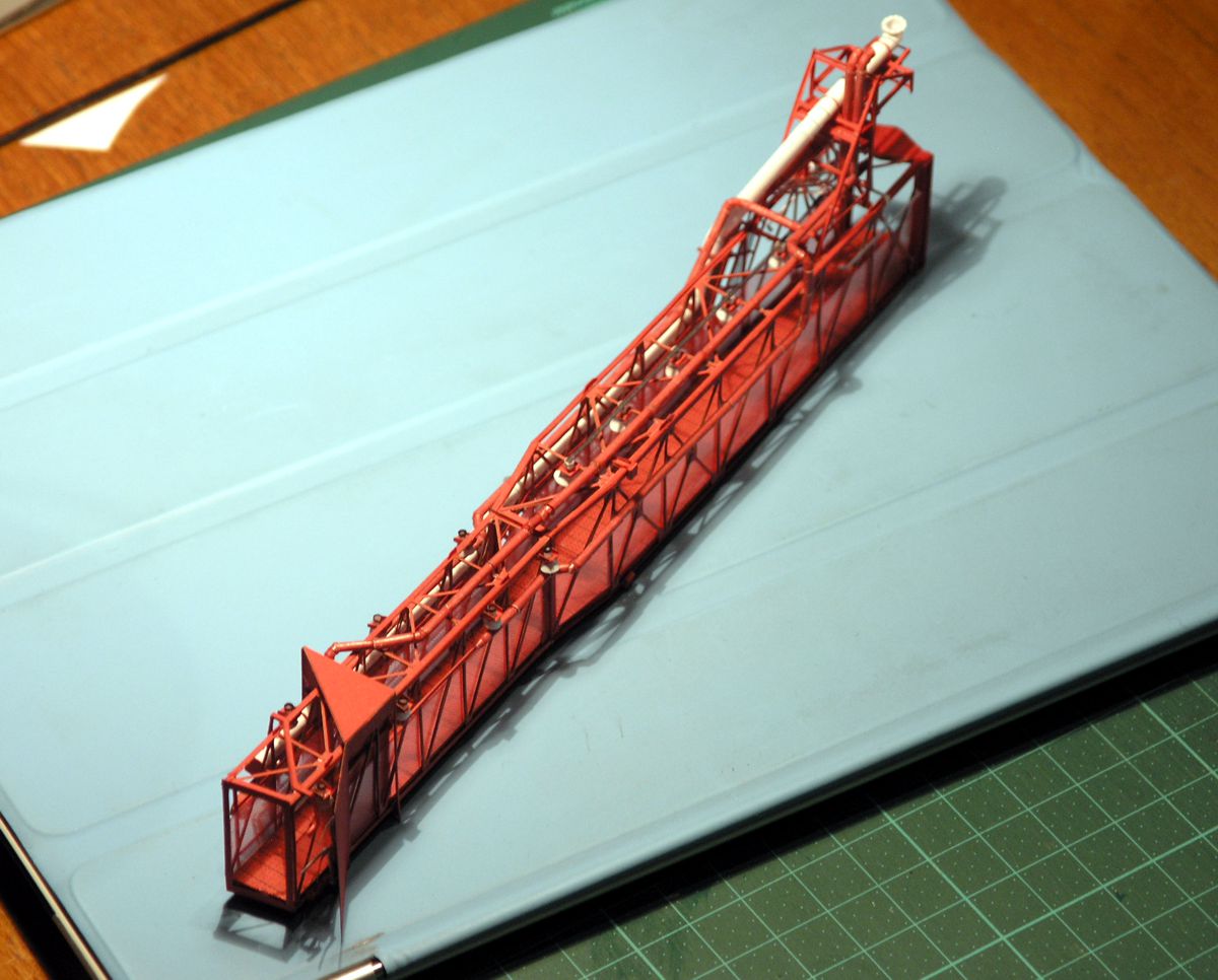
Water deluge pipes
The jungle of plumbing is slowly clearing, while at the same time the swing arm already shows a certain complexity. At least it's getting more and more difficult to touch the thing without another damage report to the insurance company. The left water pipe is now finished, it also tapers further forward from 6" to 4" in order to slip forward between the latticework and the MSS cover.
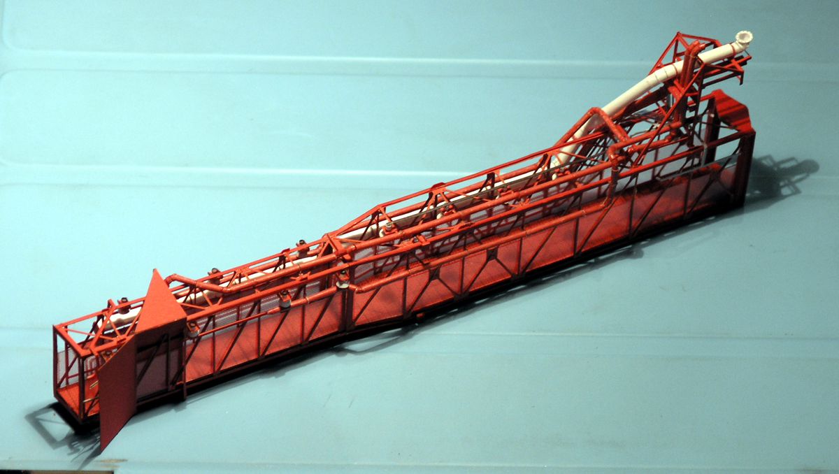
Water deluge pipes
At the support tree, the two water pipes rise to the top, in order to pass into flexible hoses to continue to the LUT, which will be a bit challenging from a cardboard point of view. Ideas in this regard are gladly welcome.
The pipe sections in front of the MSS cover that continue to the White Room are still missing, as it makes sense not to fix them until the corpus of the White Room has been attached. Aside from that the tube chapter is closed. At the swing arm only the skid and parts of the railing at the back of the hinge are missing. Both will be added in the end, because they are vulnerable and actually only in the way.
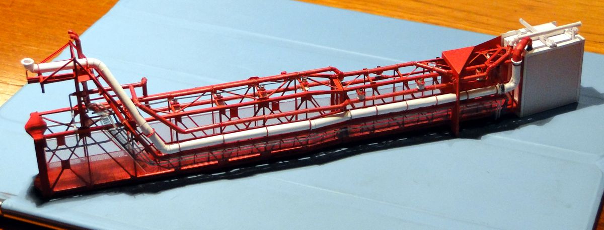
Water deluge pipes
The tube and cable folklore in front of the MSS cover is finished; as you can see, a lot is going on there. The air condition tube ends with a vacuum cleaner nozzle-like structure on the roof of the White Room, and the upper water pipe continues above as a blind ending pipe. As I said, I guess it was some kind of sprinkler/emergency device.
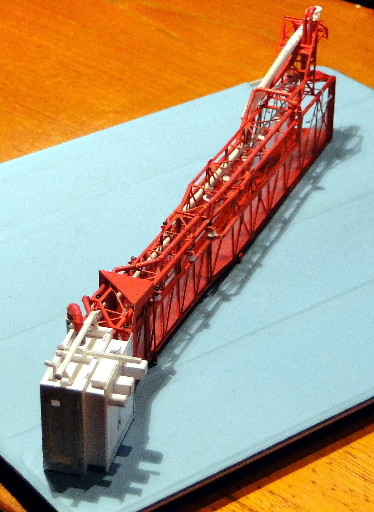
White Room
The White Room Body is also finished (except for the rear floor plate, which was movable for the middle part of the White Room, that was stretched like an accordion). White is the witch color of paper modeling. You can see every tiny mistake, I'm not even talking about traces of glue. During the assembly process a lot went wrong, I will redesign a few parts to make the assembly a walk in the park for the following generations of model makers
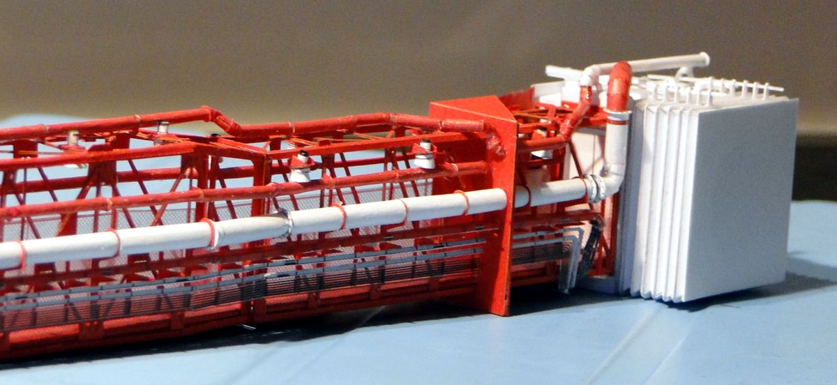
White Room
The accordion. I quickly discarded my original idea of making the thing moveable. After completion, you'll be happy if you never have to touch the swing arm again. Squeezing it would give your nerves the rest. The curtain rods are super-glue-hardened paper strips threaded through micro openings in the hangers.
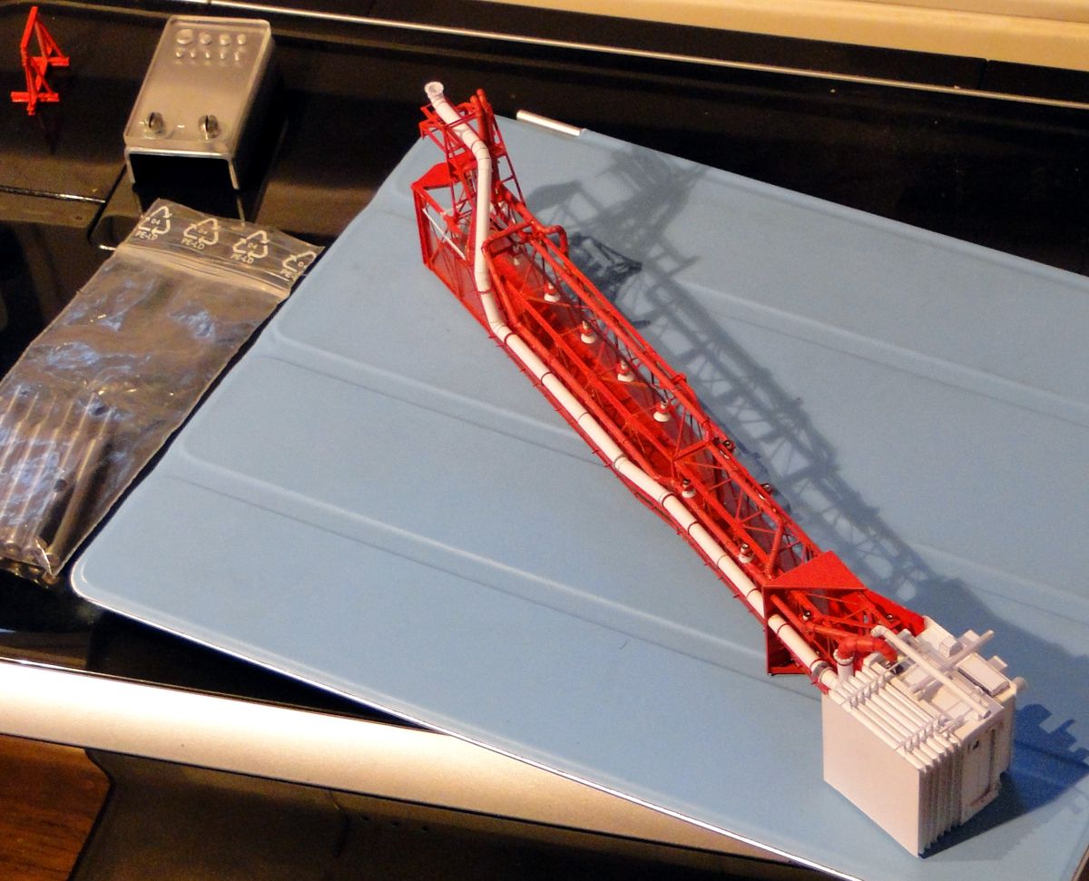
White Room
Thanks to Roberts Punch & Die set to the left this is a relaxed walk. Apropos Robert: There are no transparent credit card blanks. Thankfully he sent me a pure white one, which is quite good to work with. But he stays tuned and experiments with exotic transparent materials and his laser cutter.
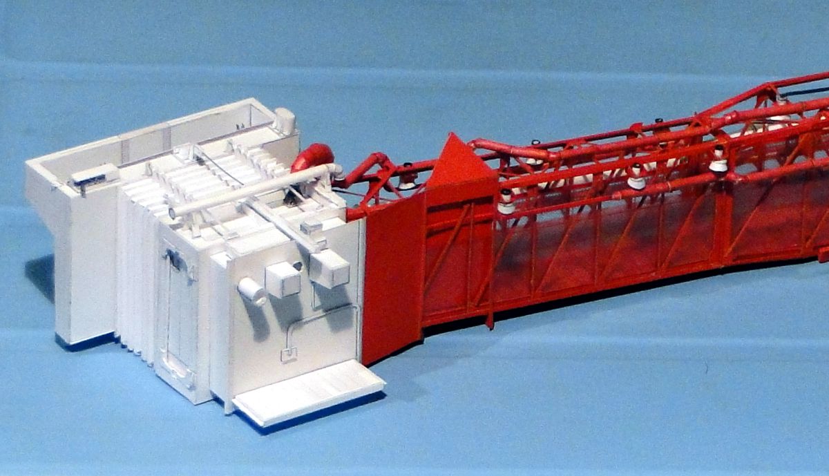
White Room
I've been asked if you can look inside the White Room. Well ... of course you can look inside through the two windows, each about 2mm in size - one circular at the back between the two wart-like rubbers, the second in the right door wing at the exit into nowhere. But you won't be able to see too much, because it's dark inside.
But I have to admit that I cancelled the interior - from the front it would visible through the crawling opening into the Apollo capsule, but it would have required that the front frames were all made in hollow frames, which would have increased the stability immeasurably into the fragile. Moreover, the connector was closed by a cover during the rest periods of the LUT in order to avoid attracting unpleasant residents. And during the docking time to the Apollo capsule the view into the interior was naturally blocked by the physical presence of the Apollo vehicle.
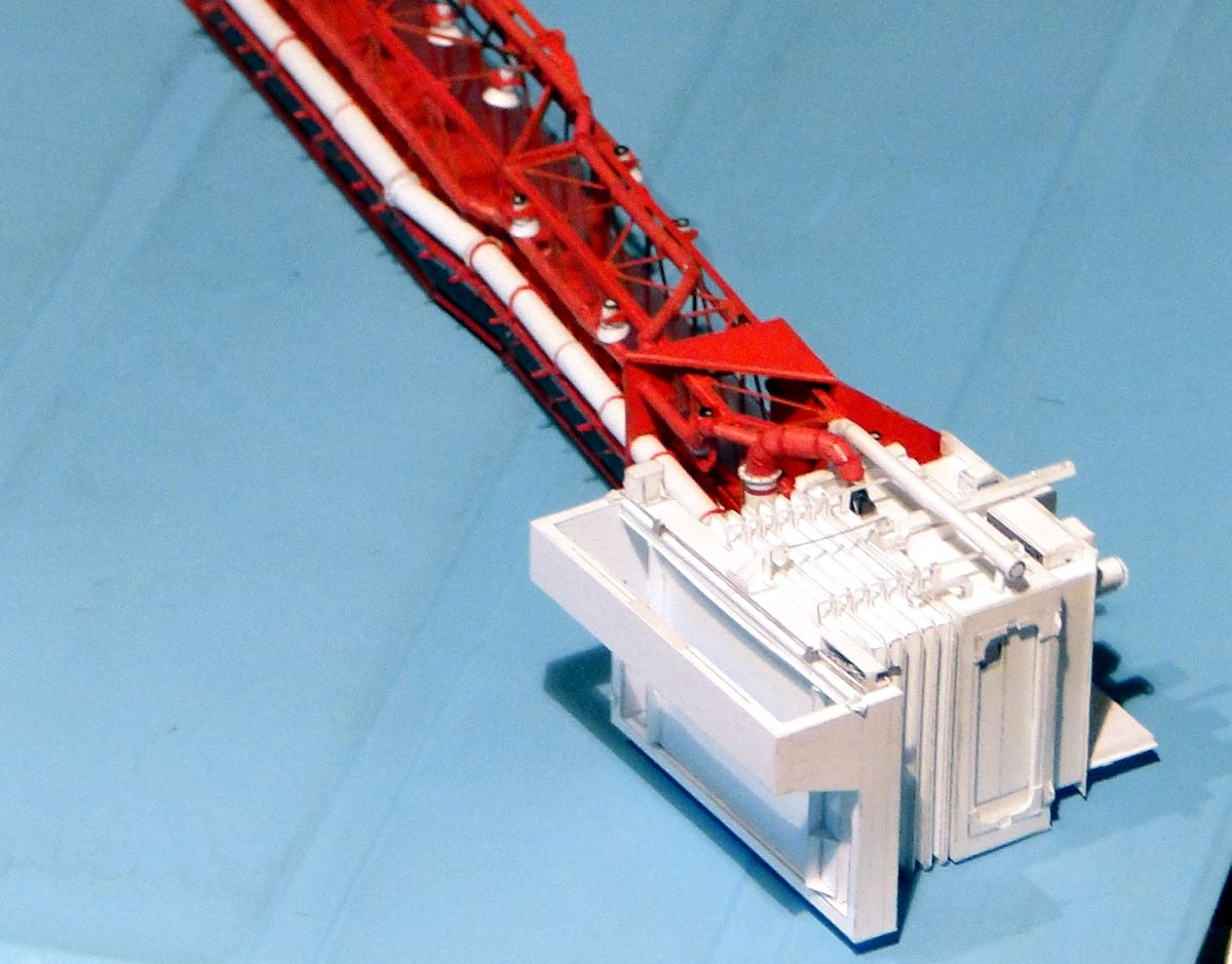
White Room
The housing of the connector is now finished. The camera finds it somewhat difficult to capture the details because the white light outshines everything in the bright lamplight. I tried to take pictures with indirect lighting, but then the camera doesn't really get along with the focus ...
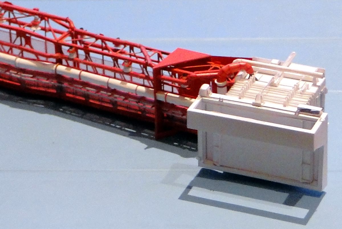
White Room
... here one of the better results. The White Room can be placed comfortably on your palm, and some parts are really tiny - the smallest is 0.16 mm². But once the arm is finished, I'll take pictures with my daughter's professional camera.
White Room
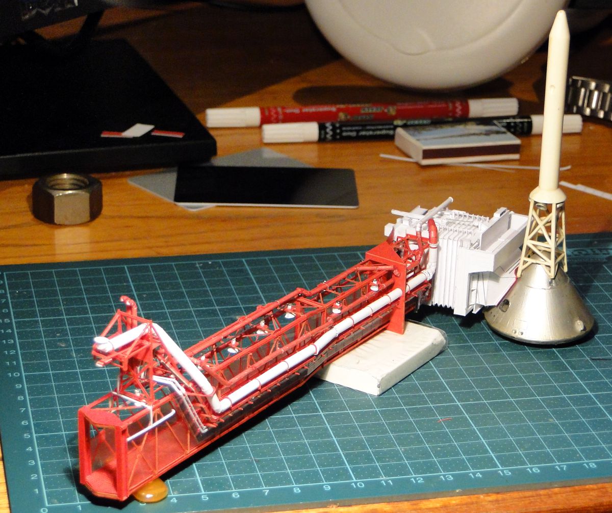
First fitting with the Revell Apollo. Sits, fits, wobbles and has air. I have to say, Rhino is really impressive. On the left in the background my relic - a nut from LUT 1, Level 380. A good star for a LUT project
White Room
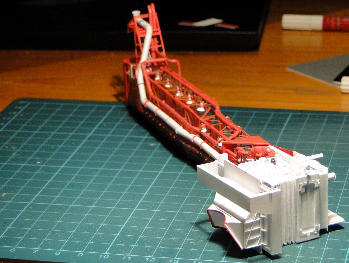
The (optional) structural applications on the side wall of the connector. You have to research deep in your conscience and ambition whether you really want to do this to yourself. The rule is quite simple: If you reach 99% perfection or above makes everyone kneeling in adoration. Everything below makes you cry.

White Room
Close up, to give the cable sausage the honor, that flows out of the cable tray and winds to the other side together with the hydraulic and compressed air lines under the bottom of the swing arm. Room for hyper improvements, especially their continuation on the roof of the White Room.
As you can see, a swing arm is assembled in no time. And the CM-Service arm is certainly the most complex at the LUT. I omitted the bracer cable and the two fences at the entrance of the hinge, both only make sense in the context of the LUT, and are highly vulnerable.
However, the part is quite tip-heavy, and tilts forward. The fact that the real arm remains standing on the supports is partly due to the retracted accordion and partly to the suspension, which was fixed somewhere on the roof in the hangar. Because this is rather unfavorable for the model, I used a base made of a rest of transparent foil and placed under the accordion...
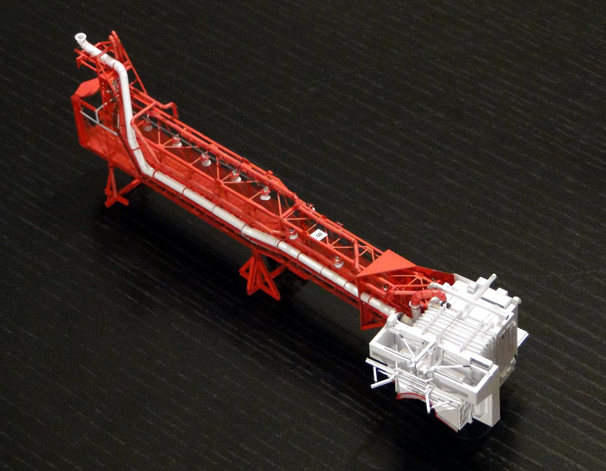
Finished Command Module Service Arm
The stabilizer is quite a framework, and looks very confused in its final state. Especially in comparison with early versions, you get the impression that a lot of improvisation talent and creativity have come to top form here. Unfortunately there is no continuation of the fit test - which is due to the fact that the rods of the LES on the Revell model are a bit too thick, and therefore the stabilizer can only be attached at the risk of his physique.
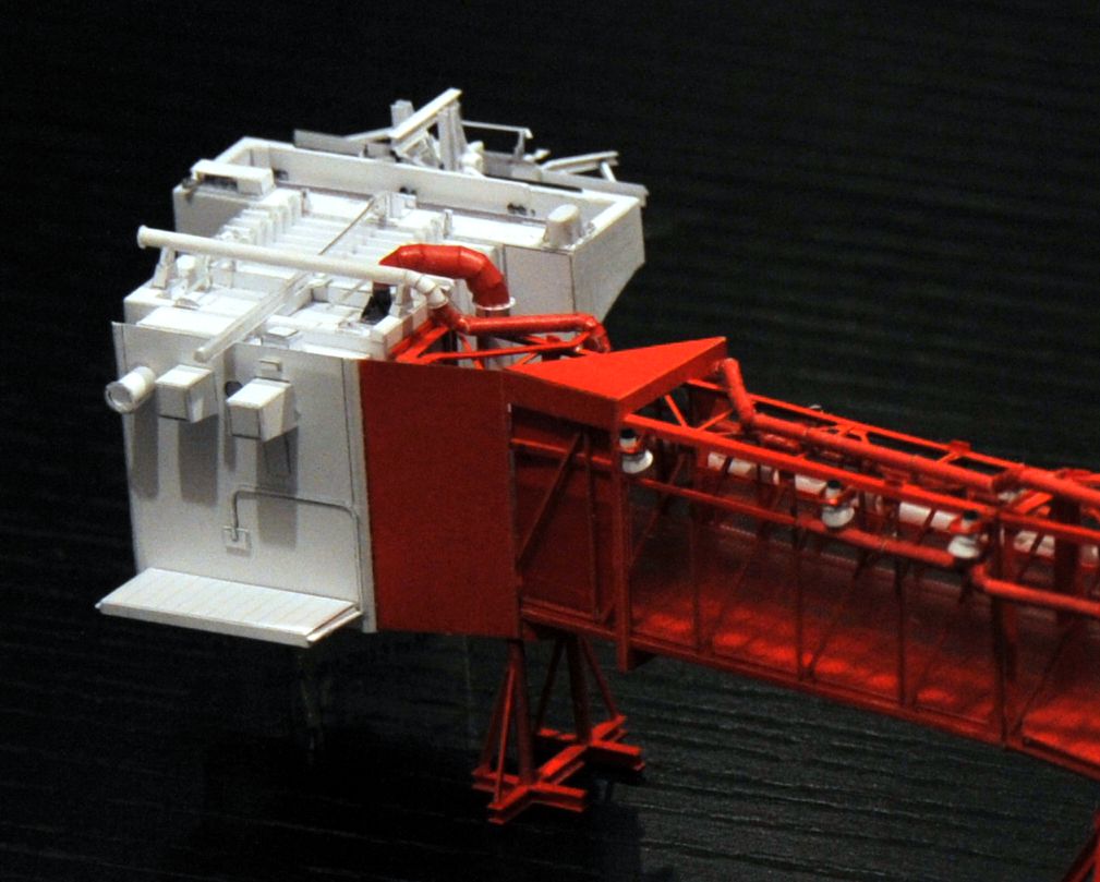
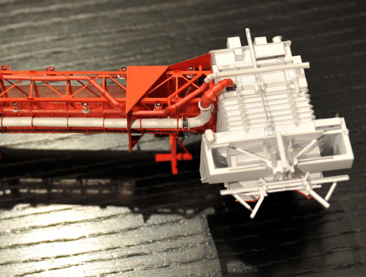
Finished Command Module Service Arm
And with this little review I retreat back into the virtual. At the CM-Service Arm kit there are terrible construction errors, about which I graciously spread the mantle of silence. The errors occurred during the transfer to CorelDRAW, and have a lot to do with mirror-invertedness and stupidity of the constructor. As soon as the update is available, I will inform you
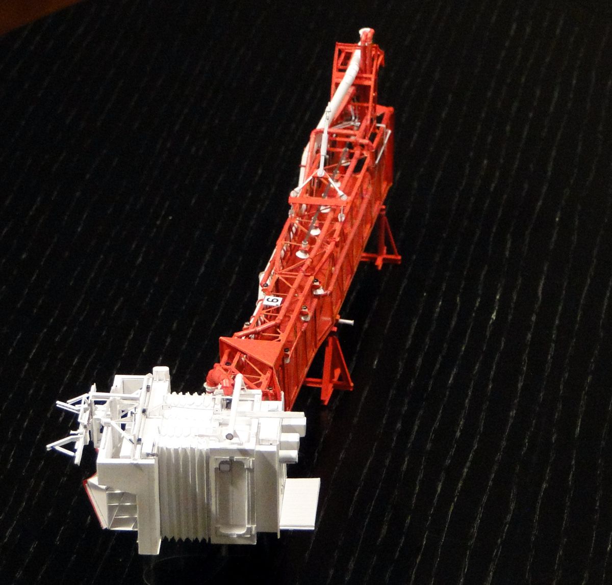
Finished Command Module Service Arm
If only I could stop. The remaining particles stared at me reproachfully, so I pitied myself, and added the bracer cable, the hinge screens as well as a few other tiny ones. The number plate was updated as well, because there were two of them - maybe even three, at the bottom of the arm another one would be quite plausible, but I couldn't find any photo of it.
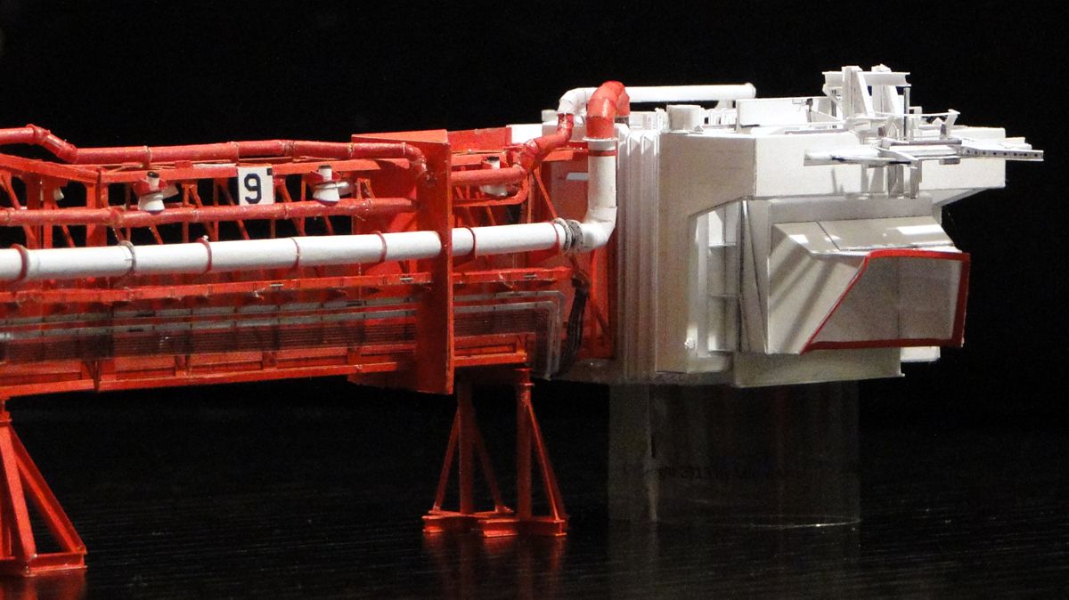
Finished Command Module Service Arm
So here's the second one perfectly visible in the picture. The black corner in the upper right corner contained the serial number of the LUT - in our case a 1, which people with ingrown microscopes in the eye sockets can easily recognize. But now the CM-Service arm is irrevocably finished. And the updated version of the instructions and the kit can be found here.


